Switching characteristics of SCR Read Electric Vehicle Circuit Diagram One useful application of the SCR is in DC-powered 'alarm' circuits that use self-interrupting loads such as bells or buzzers; these loads comprise a solenoid and a series switch, and give an action in which the solenoid first shoots forward via the closed switch, and in doing so, forces the switch to open, thus making the solenoid fall back and re-close the switch, thus restarting the action

Using a hybrid relay based on both components (relay/Triac), instead of only a relay, have the following benefits: V. MAIN. applied to relay • Relay reliability: The load inrush current is managed by the silicon switch, safely thanks to its high current capability. It also increases the relay lifetime, which only drives the steady-state current.
Driving/Running and Controlling High Power loads with Microcontrollers Circuit Diagram
contactor, an SCR provides fast response and high resolution as well as the ability to limit current and regulate load voltage, current or power. Disadvantages to using an SCR Power Control can include low power factor, high harmonic currents and radio frequency interference (RFI) when using phase-fired power controllers.
An SCR (silicon controlled rectifier, or thyristor) is a semiconductor switching device, with two power terminals, called the anode (A) and cathode (K) and one control terminal called the gate (G). If terminal K is taken positive with respect to A, the SCR is reverse biased and will block current from flowing.
PDF How to implement an SCR or a Triac in hybrid relay applications ... Circuit Diagram
However, it is possible to use the TRIAC as a driver for another switching device, as shown in Figure 11. This scheme allows a low-power SSR to control high-current loads by means of external, high-power SCRs. Figure 11 shows how we can use a TRIAC along with three resistors to produce the two controlling signals of Figure 9(B).
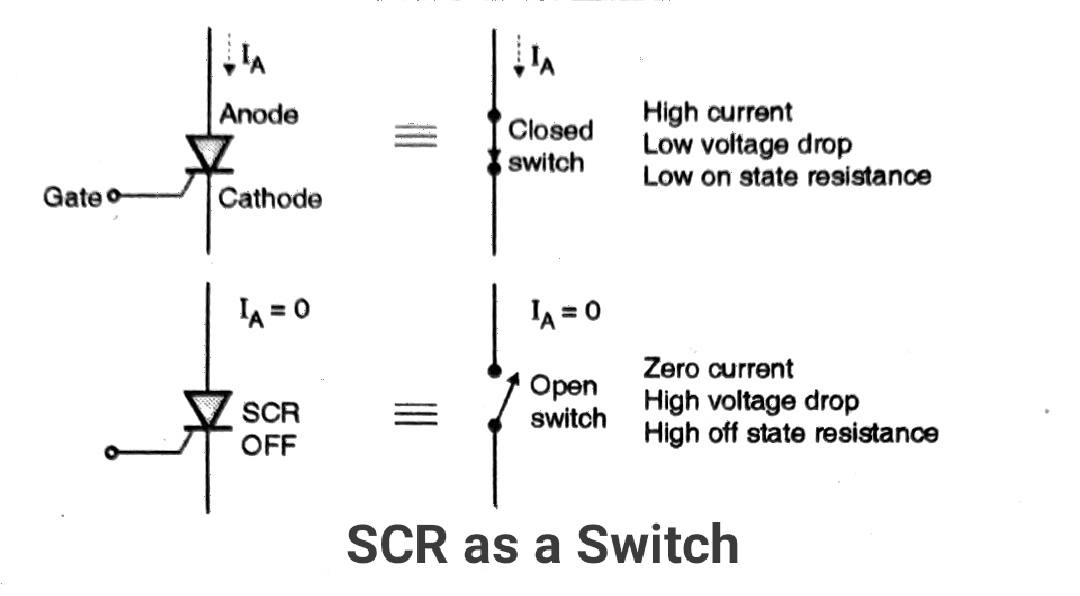
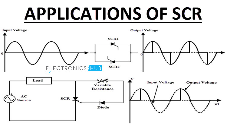
425 AMP THREE-PHASE SCR CONTROLLER 1.0 INTRODUCTION TO SCR POWER CONTROL Since the development of SCR power controllers in the late 1950™s, the power handling capabilities of SCR™s (silicon controlled rectifiers) have advanced from a few hundred watts to many megawatts. So, too, the use of SCR power controllers in industrial applications has The below figure shows the application of an SCR as a switch to ON and OFF the power supplied to the load. The AC power supplied to the load is controlled by applying alternate triggering pulses to the SCR. The resistors R1 and R2 protect the diodes D1 and D2 respectively. The resistor R limits the gate current flow.